L2VPN in VMC on AWS

I generally try to write about what I am working on at any given time. This month has involved working on connecting applications which have a hard requirement to span Layer 2 from the VMware Cloud on AWS environment to a customers on premises datacenter. While I normally try to bring sanity to these environments and push for a refactoring/replatforming exercise, for may of the teams I assist, this is just not an option, or is a long term project. Part of the value of VMC on AWS is the flexibility of the solution while bringing environments closer to cloud native resources.

Design requirements

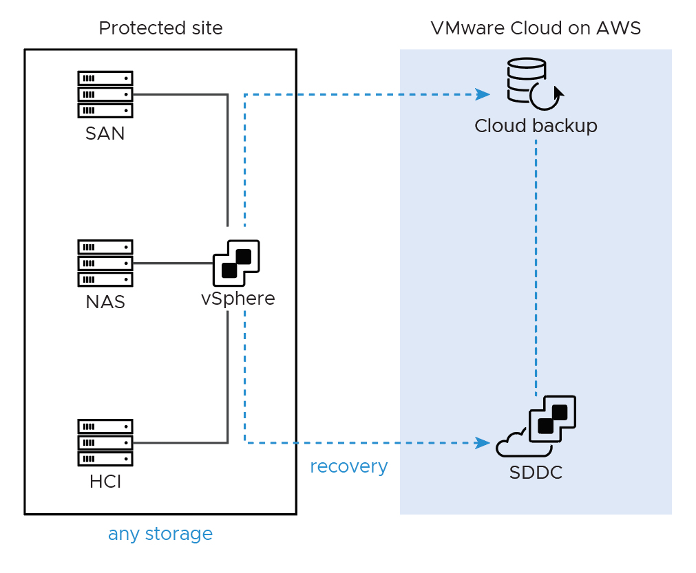
For this particular use case we were working to connect a single non-x86 system running a database to the VMC environment, with no opportunity to migrate/convert the database to something we could run in VMC or a native cloud provider. Since this is business continuity design exercise, every attempt must be made to mirror production. All x86 virtual systems will be replicated to the VMC environment, and the remaining system will sit in a co-location datacenter in the same region. Connectivity between the VMC environment and the co-location datacenter is accomplished by a direct connect which is assumed to be connected already..

Setting up the VMC environment.

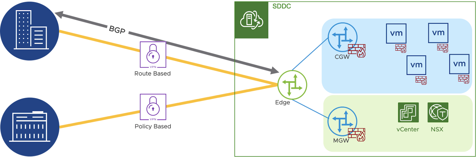
Once logged into the VMC on AWS environment, select “View Details” on the SDDC to be connected to. Under the “Networking & Security” Tab, select “VPN” and then “Layer 2”. Select “Add VPN Tunnel”. In this case since we are going over a direct connect we chose the provided Private IP address, and our remote public IP was the termination of the direct connect at the colo.

After saving, expand the VPN and download the config, you will need this soon.  You will also want to take note of the “Local IP Address” for the VMC environment.  This can be obtained by clicking the info icon, and then copy the Local Gateway IP (Blocked here for security).

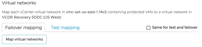
Next select “Segments” in the left panel and “Add Segment”. Enter a segment name that will make sense for the environment, set type to “Extended”, and select a tunnel ID, it must be unique to the extended segments in your VMC SDDC. 

NSX Edge deployment on-prem/colo

The remaining work will be done from the local or colo vcenter server.  Download the NSX-T Datacenter OVA, and begin the deploy process to your local vCenter.

Select Networks

At the “Select Networks” section, you need to determine your network topology.  In this case we are running VLAN’s on the dvSwitch, so each port is treated as an access port.  This becomes critical in the next screen.  For the sake of simplicity I have labeled the Port Groups as what they are used for.

Network 0 – For accessing the OVA’s cli and web management interface.

Network 1 – The management interface for the VPN.

Network 2 – This is the network where the layer 2 traffic will flow.

Network 3 – This is for HA traffic if you are running multiple edges for redundancy, not used in this case but still required.

Customize Template

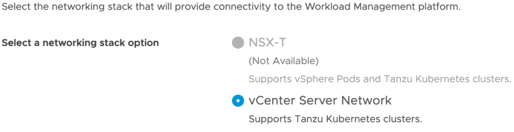
Put in passwords and usernames as required until you come to the Manager area.  There is no NSX manager since we are deploying as an autonomous edge so skip everything except make sure you put a check in the Autonomous Edge.

Under network properties enter a hostname, and the management IP information.  This should be an IP on the Management network as above.

In the External section, as stated above, we are using VLANs at the portgroup level which effectively makes the port an access port, so in the box we need to make sure we set the VLAN to 0 and complete as below.  This is our uplink configuration so make sure you select eth1 in this case.

Ignore Internal and HA sections and the rest of the inputs, and select next, review, and then finish to deploy.

Configure the Autonomous Edge and Tunnel

When the NSX Autonomous edge has finished deploying, bring up the web interface and login as admin.  Select L2VPN and ADD SESSION, and fill in the fields.

Session Name – Input a name that makes sense.

Admin Status – Leave as Enabled.

Local IP – The external uplink IP we previously gave when installing the Autonomous Edge.

Remote IP – The Local Gateway IP we previously obtained from the VMC Environment.

Peer Code – This is found in the config file we previously downloaded, paste the text here.

Save and select PORT and Add Port, and fill in the fields

 Port Name – Input a name that makes sense (This is for the trunk so likely include that)

Subnet – Leave this blank

VLAN – 0 (Remember we are terminating the VLAN’s at the port group so these are access ports)

Exit Interface – eth2 (our trunk port)

Save and return to the L2VPN screen and select ATTACH PORT.

Session – Select the session we created previously

Port – Select the Port we just created.

Tunnel ID – this is the same as the Tunnel ID we created on the VMC on AWS side.

Once you attach the status should come up on both ends, and you are now connected.  For test purposes it is usually wise to put a test machine on each end of the tunnel, and run a few network tests.  This is not as common a use case, but it is helpful for environments where L2 tunneling is required.  

For more information please look at the documentation VMware publishes and the blog post I used as well while working on the solution.

VMware Documentation 

Configure an Extended Segment for the Layer 2 VPN

Install and Configure the On-Premises NSX Edge

Blog Post

Setting Up L2VPN in VMC on AWS

L2VPN in VMC on AWS

VMware Cloud Disaster Recovery – Advanced Solutions Design

Previously I talked about VCDR (VMware Cloud Disaster Disaster Recovery) Solutions Validation, and how to properly run a proof of concept.  The reality is that while it would be nice if all applications were as straightforward as our wordpress example, there are often far more complex applications requiring far more advanced designs for a disaster recovery plan to be successful.

External Network Dependencies

For many applications, even in modern datacenters, external network dependencies, or even Virtual Machines which are too large for traditional replication solutions can create challenges when creating disaster recovery plans.

To solve for this, 3rd party partners may be used to provide array or other host based replication services.  This solution requires far more effort on the part of the managed services partner, or the DR Admin.  Since the physical or too large for VCDR workloads cannot be orchestrated through the traditional SaaS orchestrator, there is an additional requirement to both test, and manually failing over.  A Layer 2 VPN between the VMware Cloud Environment and the partner location provides the connectivity for the applications running in both environments.

Script VM

For the more complex VM only environments, some scripts may need to be run during the test and recovery phases.Similar to bootstrap scripts for operating system provisioning, the scripts may be used for basic or even more advanced configuration changes.

The script VM should be an administrative or management server which is either the first VM started in the test recovery, or production recovery plans.  Separate VMs may be designated for testing versus production recovery as well, enabling further isolated testing one of the biggest value propositions of the solution.  Further specific documentation is located here, Configure Script VM.

Extending into VMC on AWS

WIth more complex architectures, it often makes sense to consider a mixed DR scenario.  In these cases, moving some of the applications to the VMC on AWS environment to run permanently, or leveraging another method for replicating outside the traditional VCDR SaaS orchestrator may be warranted.  While this does present some risk again since this is not tested with the rest of the VCDR environment, it does provide for additional options.  

With the recent addition of Cloud to Cloud DR, more options were made available for complex disaster recovery solutions.  Once an environment has been migrated full time to VMC on AWS, VCDR can be leveraged as a cost effective backup solution between reasons without a need to refactor applications.

Even in advanced DR scenarios, the VCDR solution is one of the more cost effective and user friendly available.  With the simplicity of the VMC on AWS cloud based interface, and policy based protection and recovery plans, even more complex environments can take advantage of the automated testing and low management overhead.  The best and most impactful DR solution is the one which is tested and which will successful recover in the event it is needed.

VMware Cloud Disaster Recovery – Advanced Solutions Design

VMware Cloud Disaster Recovery – Solution Validation

In the previous post, I talked about the VCDR (VMware Cloud Disaster Recovery) solution overview.  The best way to determine if a solution is the right fit is to validate the solution in a similar environment to where it might run in production. For this post, the focus is on validating the solution and ensuring a successful POC (Proof of Concept) or Pilot.  As always, please contact me or your local VMware team if you would like to hear more, or have an opportunity to test this out in your environment.

Successful Validation Plans

The key to any successful validation plan is proper planning.  For testing, it is always best to look for 2-3 use cases at most to be tested.  In the case of VCDR, generally the following tests make the most sense.

  • Successfully recover one or two windows or Linux web servers – Web servers are usually fairly simple to test initially.  Linux servers are generally faster to build and the license is open source making for a good test case.
  • Successfully recover a 3-tier app – Often time using two to three Linux VM’s running a Web Server, an App Server, and a Database Server, something such as WordPress or similar running on Linux, is often a good candidate since it is simple to setup and makes for a set of virtual machines, which must be connected or the app will not work properly.
  • An addition or an alternative for the 3-tier app would be any similar internal application which is a copy of production or a development system which could be leveraged for testing.

The purpose of the test is to demonstrate replication of the virtual machines into the DR (Disaster Recovery) environment; the actual application is less relevant than validating the functionality of the solution.

Setting up the “on premises” environment

It is critical for a POC to never connect production. POC’s are very much meant to be a demonstration of how things might work within a lab. The POC environment is for a finite period, typically 14 days or less, just enough to demonstrate a few simple tests.

The Lab setup for this should be very simple. A single vSphere host, or a very small isolated cluster will suffice, with a vCenter instance and the test application installed. A small OVA will be installed in the environment as a part of the POC so there should be sufficient capacity for that as well.

One of the most critical prerequisites to be addressed before beginning is the network connectivity. For most POC’s it is recommended to use a Route based VPN connection to isolate traffic, although policy based could work.  This will generally require engaging the network and firewall teams to prepare the environment.

Protecting the test workloads

The test cases above should be agreed upon.  The following is a formalized test plan that will be included in the POC test document.

  1. Demonstrate application protection and DR testing.  This will be accomplished by the following.
    1. Protect a single 3 tier application such as WordPress or similar from the lab environment into the VCDR environment.
    2. Complete up to 2 Full DR Recovery Tests and demonstrate the application running in the VCDR Pilot Light Environment.

The POC is very straight forward.  Simply deploy the VCDR Connector OVA to your lab vCenter, register the lab vCenter with the VCDR environment, and create the first protection group. 

In the case of a POC, there will only be a single protection group.  We will add the three WordPress virtual machines to our demo using a pattern name based on how we named them.

Creating a DR Plan requires mapping the protected site, the lab in this case, resources to resources in our cloud DR environment.  

A key decision point is in the virtual network.  You can choose to use the same network mappings for failover and testing.  In the POC we can use the same networks, but for a production deployment we want to ensure they are separate so we can run our tests in a bubble without impacting production workloads.

Once we are all set up, the last thing to do is replicate the protection group, and then we can run our failover testing into the VMC on AWS nodes connected as VCDR Pilot Light nodes.

While this is fairly straightforward, the key to any successful POC is to have very specific success criteria.  Be sure to understand what you want to test and how you will show a successful outcome.  Provided the 3-tiered app model fits your business model, this is a great use case to start with to validate the solution and get some hands on experience.  For more hands on experience, check out our Hands on Lab, https://docs.hol.vmware.com/HOL-2021/hol-2193-01-ism_html_en/, and be sure to come back for more VMC on AWS as we continue to look at the direction the cloud continues to go and the future of VMware. 

VMware Cloud Disaster Recovery – Solution Validation

VMware Cloud Disaster Recovery – Solution Overview

In November of 2020, I changed roles at VMware to join the VMware Cloud on AWS team as a Cloud Solutions Architect.  Going forward, I intend to work on a few posts related to the VMware Cloud product set, and cloud architecture.  I am a perpetual learner, so this is my way of sharing what I am working on. I welcome comments and feedback as I share. Many of the graphics in this post were taken from the VMware VCDR Documentation.

To start with I wanted to focus on VCDR (VMware Cloud Disaster Recovery), based on the Datrium acquisition.  To be clear, this is not marketing fluff, this is not a corporate perspective, this is my personal opinion based on the time I have spent working with VMware customers on the VCDR product.  I promise you this may sound like marketecture, but this article lays the important foundation for the next several.

The Problem

DR (Disaster Recovery) is not an exciting topic.  It is basically the equivalent to buying life insurance; you know you should do it, but usually it is a low priority, until it isn’t.  We often think of disasters as fire, flood, earthquake, and other natural disasters, but recently malware has become the largest problem requiring a good DR plan.  

When a system, or systems, are compromised, it is likely that not only the file systems are compromised, but also the backups, mount points, and even the DR location.  Prevention is the best way to solve this issue, but assuming you are attacked, a good DR plan is critical to restoring services quickly and securely.  

The Overview

VCDR uniquely solves this problem with immutable (read only/unchangeable) backups and continuous automated compliance checking.   

The biggest challenge is that when we do backups we are generally appending changed blocks which makes for a far more efficient backup solution. This lowers the cost, and the time to backup while still providing a point in time recovery solution. When the backup is compromised, the best case in this option is to go back to a time before there was malware, assuming it is not infected somehow.

VCDR solves this problem by creating an immutable point in time copy of the data. Since each point in time copy is isolated from the others, malware cannot infect the previous points. The system can then pull together all the partial backups to make what appears to be a full backup at any given point. Since this is all being handled as a service, recovery is near instant, and the recovery admin can recover from as many points as needed to find the best point to restore to. 

As a Service

The promise of everything as a service seems like a great idea, but in practice it can create some challenges. It requires that we trust the service, and that we regularly test the service. VCDR is no exception. Because this is a part of the VMware Cloud portfolio, this enables adjacency to other VMware Cloud services, in particular VMware Cloud on AWS. Leveraging the Pilot Light service, some applications which are critical for recovery can be recovered directly to a cloud based service while the less critical services can be brought back online in the Datacenter once the problems are mitigated.

By providing a warm DR location, the costs are significantly mitigated, and by using the “as a service” model, many of the lower value tasks such as patching and server management are handled by the service owners, VMware in this case.

Some cool details

Aside from the immutable backups, the SaaS orchestrator, and the Scale-out Cloud File System provide a significant edge for many users. The SaaS orchestrator provides a simple web interface to configure production groups.  Setting the protection groups by name patterns, or exclusion lists gives DR admins a simple setup, and no need to recover an onsite system, or log into a new site before doing recovery.  

The Scale-out Cloud File System is simply an object store which provides for far greater scale, as the name implies. For instant power on to test virtual machines, this cloud based file system will mitigate the need for the additional configuration during a declared disaster. Once the appropriate recovery point is identified, simply migrate the powered on Virtual Machine back to the datacenter, or run it in the Pilot Light environment in VMC on AWS while the host is being prepared to receive the recovered VM.

Moving forward I will explore test cases for the VCDR service, where it fits within the Backup, Site Recovery Manager/Site Recovery service continuum, and even dig into the VMware Cloud on AWS services. 

VMware Cloud Disaster Recovery – Solution Overview

Installing VMware Tanzu Basic on vSphere 7

With VMware Tanzu becoming more critical to the VMware Strategy, I thought I would see what it is like to install in my lab with out any experience on this specific product. I plan to write a few more posts about the experience and how it relates to VMware Cloud strategy. As a disclaimer this was done with nested virtualization, so this is not a performance test. William Lam wrote a post on an automated deployment, but I wanted to have a better understanding to share. To get myself started I watched Cormac Hogan’s video on the implementation.

Assuming the prerequisites are met which is covered in several youtube videos and other blogs, start with selecting “Workload Management” from the main menu in the vCenter web client. The initial choice is allows you to select NSX-T, if installed, or you will need to use HAProxy for the vCenter Network.

On the next screen, select your cluster, next and then choose your control plane size. For a lab deployment Tiny should suffice, depending on how many workloads to be deployed in the environment. On the next screen choose your storage policy, in my lab I am using vSAN to simplify things.

For the Load Balancer section, you just need to give it a name, something simple works and select HAProxy as the type. The Data Plane API Address is the IP of the HAProxy you setup, with a default port of 5556. Put in the username and password you put in when setting up HAProxy. The Virtual IP Address Range you should pick something in the workload network, separate from the management network and something not in the DHCP scope.

In the “Server Certificate Authority” you will need to SSH into the HAProxy VM, and copy the output of “cat /etc/haproxy/ca.crt” into the field.

In the workload management section, select the management network being used for the deployment. Input the network information including the start of the IP range you want to use.

Under the workload network, select your workload network and fill in the information. This should be on a separate broadcast domain from the management network.

For the Service Network pick something that is not conflicting with your existing networks, and at least a /23 range. Add your workload network from the previous screen below.

Finally select the content library you should have subscribed to already, and finish. It will take some time to provision and you can then provision k8s workloads natively in the vSphere environment.

A couple thoughts on this, the install wasn’t too bad, but it did take a while to understand the networking configuration, and setup everything correctly. I had also assumed this would be a little more like VMware Integrated Containers. While I have some understanding of deploying workloads through k8s, installing it is a bit more learning. The next steps for me are go through the deployment a few more times, and then start testing out some workloads running.

For those of us coming from the Infrastructure side of things, this is going to be a great learning opportunity, and if you are up for the challenge, Kube Academy is an exceptional, and no cost resource to learn from the experts. For those who do not have a home lab to work with, VMware also offers a Hands on Lab, for vSphere with Tanzu at no charge as well.

Installing VMware Tanzu Basic on vSphere 7

Starlink Beta: More Performance Updates

I will be posting a video on this in the next few days for anyone who wants to create this for themselves. Please keep an eye on my playlist on Starlink for more details. For now I wanted to get a quick performance update out.

These graphs are all based on a history graph and gauge graphs from Home Assistant. In the youtube video coming out soon, I will show how to do this very quickly, and remotely. For reference, this is currently running the speed test every 1 min, after this post, I am going to adjust to run every 15 min to make the graph easier to read.

Here is a current, as of the writing of this, test. Not great but pretty good since I am still working on mounting and it is still sitting on my back porch.

Here is my dashboard for the past 24 hours. As you can see, performance is fairly solid, but what this does not show currently is the outages. It appears to randomly drop every few min to hours, which is likely due to the early stage of this test and will likely be resolved as more satellites are launched.

As always please comment if you have thoughts on testing, and check out my youtube channel for the latest videos. I will be posting more videos on how to create this monitor and plan to do some recordings of video calls, and statistics while streaming videos over Starlink to demonstrate the real world applications.

Starlink Beta: More Performance Updates

Starlink Beta: Happy New Year!

Nothing groundbreaking today, just wanted to post an update to the stats. More videos coming shortly here, https://youtube.com/playlist?list=PL3Bqge2W25PFufEOfS6dCvAsr5A7uTeMg.

Brief disclaimer on the stats. I have been busy working on some other projects, so the dish is still not mounted to the roof, it is sitting in my back yard, but I am still getting great performance for what it is.

Weekly Average (well really just a few days but whose counting) of the upload/download/latency.

24 hour graph every 1 min running speedtest-cli showing the speeds/latency.

I am working on a way to automate publishing these graphs daily to share so others can see them in real(ish) time. Stay tuned, and share with anyone you know who might be interested. This is really a community effort to help make internet access better for us all, so anything we can all do together to improve and provide better feedback is good for us all.

Starlink Beta: Happy New Year!

Starlink Beta: The Good, The Bad, And The Ugly

I was recently invited to join the closed beta for SpaceX Starlink satellite internet. Over the coming months, I plan to document what I learn, the good, the bad, and the ugly. I will also be posting videos when appropriate on my personal youtube channel. For full disclosure, I am not receiving any compensation for this, but I am an employee of VMware, will be using VMware products where relevant, I will do my best to remain agnostic where possible.

In order to appropriately test this solution, three variables are highly critical.

  • Download speed – How fast can you retrieve things from the internet, important for streaming television and music.
  • Upload speed – How fast can you send things out over the internet, particularly important for online gaming and video calls.
  • Latency – How long does it take traffic to make a round trip from you to your virtual destination and return, critical for voice, video, gaming, basically anything you want to do on the modern internet.

To set up the appropriate test environment I needed an isolated test network that would not impact my current production internet where my family works and plays, but also to be able to access that network securely to review the results. I also needed historical data on the performance as outlined above.

Remote Access

For the remote access, I initially set up port forwarding on my own personal router which I used to bypass the wifi-router that came with the Starlink beta. After testing, and contacting support, it was determined this is on the roadmap but not currently available. I then tried using publicly available cloud-based services for remote connectivity. This was acceptable, but much too slow, mostly due to issues on the Starlink side. I finally settled on leveraging my home wireguard VPN server and a wireguard client on a Linux server running on the Starlink network, effectively bridging the two networks with significant security restrictions, similar to the picture below.

The procedure to install and configure both the server and clients for wireguard can be found at https://www.wireguard.com/. I personally run the Linux Server Wireguard Docker image for my server.

In order to access the test network, I leave the VPN on the Starlink Test Linux Server always connected. I can then VPN into the local VPN server on the production network and then access the VPN interface of the Test Linux Server where I am running my graphing. When I have more time I will add the static routes to my firewall but for now this seems to work well.

Performance Monitoring

Performance monitoring over time was a particular challenge. My original thought was to leverage one of the speedtest CLI scripts, output to a CSV file, and use Python to display that in a website. After some research though and several failed tests, I discovered https://github.com/frdmn/docker-speedtest-grafana. This is far from a perfect solution, I have had it simply stop responding several times, forcing me to restart the docker containers, but for what I need, this is a perfect and simple solution. I deployed, and testing continues, but here are some raw outputs of the script running every 1 min for the past several hours.

As you can see, the latency does have some fairly big spikes, and the speed is pretty variable. I anticipate the speeds to increase latency to decrease as more satellites are launched, which appears to be happening quarterly or more often. I have noticed regular drops every hour or two for 1-3 min, I believe this is due to handoff between satellites, and I believe it will be resolved in the next few launches.

I will write up more of the testing, and post more videos as I find new and interesting things to show, but for now, this is a solid beta product. Some of my upcoming tests will include introducing software-defined WAN products to see if it helps with latency/jitter on the connection, and bonding connections to see if a slow but stable connection can help to smooth out some of the outages.

I firmly believe this is the future of connectivity and can make the world a better place by connecting more people and allowing those living in areas with less internet access to become more self-sufficient. The opportunities are there it is up to each of us to take them and to help each other do more great things.

Starlink Beta: The Good, The Bad, And The Ugly

What working from home means for your internet and wireless: Part 2

As we discussed in part 1, internet speeds, especially now, have become vital.  While we wait out this virus, adults are working from home, students are moving to a remote learning model and families are increasing streaming activity and online gaming and video chatting. The increased use of home internet makes the need for better quality home wireless more apparent.

For many families, the internet provider leases a modem with wireless access.  This works well if you live in a small house/apartment, with just a few wireless devices.  To paraphrase the Notorious B.I.G., “Mo Devices, Mo Problems”. As we add gaming systems, work computers, school computers, streaming devices, and then throw in a few smart home devices, well you can imagine the wireless system becomes a critical service.

Wireless coverage throughout the house is the key.  In the past, one centrally located device should support up to 50 connections.  This made sense when most of what we were connecting to our home wireless included a couple laptops, and maybe a streaming device or smart TV.  As we add smart doorbells, lighting, and other devices, strong signals become more important.  

Wireless extenders can help broaden the wireless coverage.  Basically, they join the existing network and retransmit the signal.  As with all radio signal retransmitting, there is some loss of signal strength, but this is a relatively inexpensive and simple option.

Mesh wireless is a relatively new concept to solve this problem.  The basic concept is you have several wireless devices, the first of the devices plugs into your “modem” (the device your internet provider gave you) and becomes the “router”.  The remaining device can connect via wired or wireless connection and extend the network. This is different from a traditional wireless extender since it is actually using a seperate network to “extend” the primary network so there is far less loss of speed.

For larger homes and home office/small business environments, a distributed wireless system may make more sense. Many small technology companies offer implementation and management of these professional grade environments, providing regular check ins, and updating the configuration as needed.

While we will be out of this “shelter in place” situation in the near future, this has brought to light the importance of having a solid plan in place for working from home, and having more family technology usage.  The best time to start planning is now, and when our culture returns to typical rhythms and routines, those who have improved their home and small business wireless systems will be ready for new opportunities to work, learn, and enjoy their time at home.

What working from home means for your internet and wireless: Part 2

What working from home means for your internet and wireless: Part 1

Working at home is becoming the new normal highlighting the need for dependable and responsive home internet and wireless.  In this series, we will look at some of the ways we can improve our working from home experience.

Wth an increasing number of knowledge workers being asked to work from home, many are finding what is generally acceptable for their regular use can’t hold up to video conferencing, e-mail, instant messaging, and file access. As schools and colleges move to distance learning, and several family members are accessing the wireless network at the same time, dependable and responsive home internet and wireless becomes critical.

Internet speed is one of the most well known metrics;  the one providers use to charge us for their service. More speed generally helps, especially as we have more users on our home networks. Most providers are now offering up to “Gig” service, which is blazingly fast. You are likely paying based on the download speed. Generally, home internet speeds range between 50Mbps and 1Gbps.

Without going into detail, that is how we measure the amount of data that can be downloaded from the internet. For a majority of usages this is the most important number. When working from home, sharing files with our colleagues, video calling, and “uploading” anything outside our home, the upload speed becomes critical. Because you are sending more traffic out, it doesn’t take long to overwhelm your connection.

Cable providers such as Comcast and Cox tend to have slower upload speeds, typically around 10Mbps, whereas fibre internet providers such as Verizon, AT&T, and Frontier tend to have similar speeds for both upload and download. If your co-workers are complaining of poor video performance from your video conference, your upload speeds may be the culprit.

Industry experts believe the work from home movement will continue beyond our current situation.  How will your home internet support your family’s needs now and in the future?

What working from home means for your internet and wireless: Part 1